


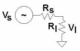
Vs = 17 Volts
Ploss= 51.6 watts per phase
Efficiency = 73.6%
efficiency. The results should be used as a guide only
a new generator will be designed.


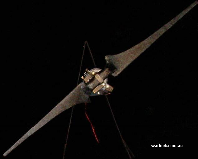
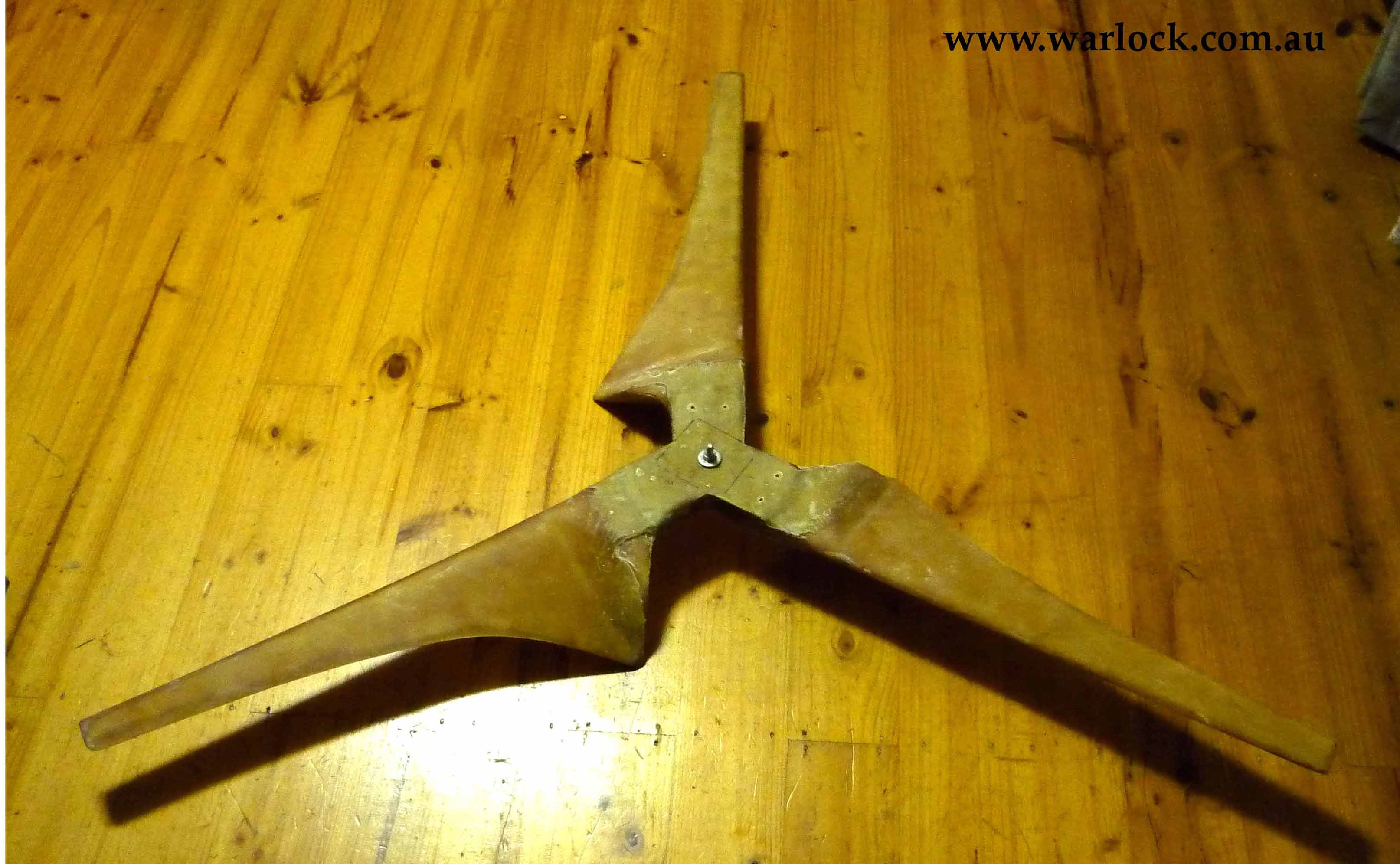
2-Blades (Carbon fibre), 1.8 Metre Diameter
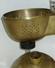
& Induction motor to PMA conversion


| Figure | Page | |
| 1 | 40 Amp car alternator rotor with magnets attached | 2 |
| 2 | 40 Amp car alternator rotor with magnets fibre glassed in place | 2 |
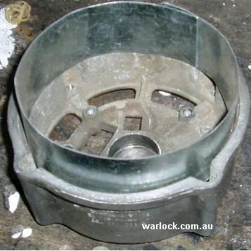
| 3 | 40 Amp car alternator stator with shielding | 3 |
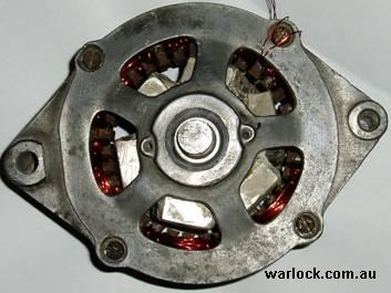
| 4 | Completed conversion of the 40 Amp car alternator | 3 |
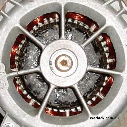
| 5 | Completed conversion a 1/4 hp induction motor | 3 |
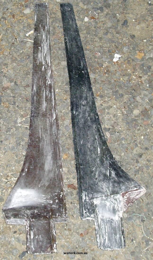
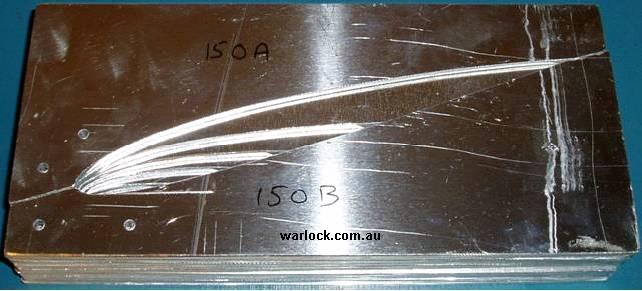
| 6 | Wind turbine airfoil cross-sections | 5 |
| 7 | Turbine airfoil cross-sections bolted to frame | 5 |
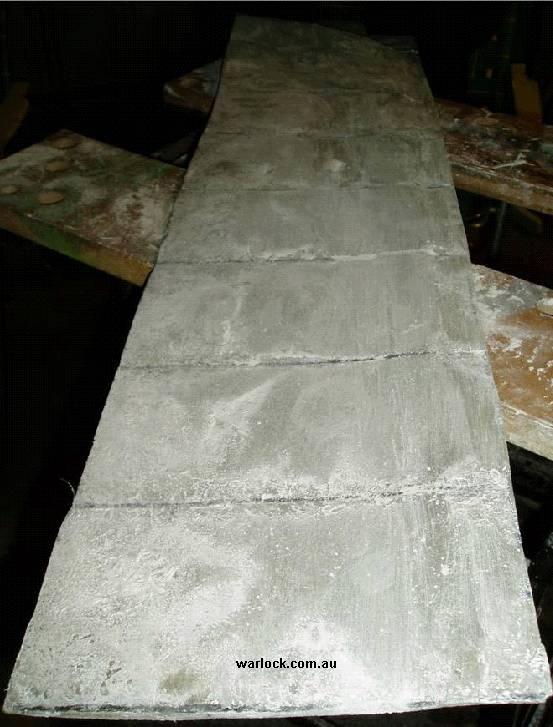
| 8 | Positive moulds of wind turbine blades | 6 |
| 9 | Negative moulds of wind turbine blades | 6 |
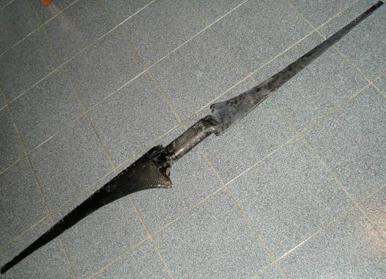
| 10 | 1.8 m blade set | 7 |
| 11 | Turbine testing | 7 |
| 12 | Measured TSR vs efficiency | 9 |
| 13 | Measured Power | 10 |


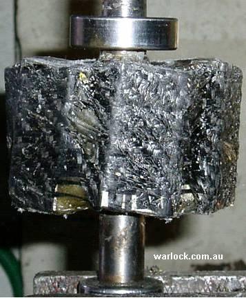
neodymium magnets.
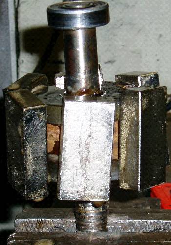
characterise the blade set. Conversion of a 40 amp car alternator to a
permanent magnet generator was attempted.


Without the sheet metal lining, significant power was lost in the aluminium.


V/R = I
I = 3 amps per phase


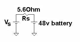

P = 144 watts per phase


wind turbine
| 25 ohm | 21.5 ohm | 15 ohm | 10 ohm | 6 ohm | |
| 30 km/h | 208 | 205 | 300 | ||
| 40 km/h | 524 | 649 | 332 | 252 | |
| 50 km/h | 950 | 981 | 1017 | 1008 | 940 |
| 60 km/h | 1953 | 2019 | 1873 | 1990 |
blades with each purchase


| 25 ohm | 21.5 ohm | 15 ohm | 10 ohm | 6 ohm | |
| 30 km/h | 820 | 766 | 809 | ||
| 40 km/h | 1302 | 1363 | 851 | 645 | |
| 50 km/h | 1753 | 1676 | 1489 | 1291 | 1105 |
| 60 km/h | 2365 | 2098 | 1744 | 1607 |
| 25 ohm | 21.5 ohm | 15 ohm | 10 ohm | 6 ohm | |
| 30 km/h | 0.23 | 0.23 | stalled | ||
| 40 km/h | 0.24 | 0.30 | 0.15 | stalled | |
| 50 km/h | 0.22 | 0.23 | 0.24 | 0.24 | stalled |
| 60 km/h | 0.27 | 0.27 | 0.25 | 0.27 |
| 25 ohm | 21.5 ohm | 15 ohm | 10 ohm | 6 ohm | |
| 30 km/h | 278 | 260 | 275 | ||
| 40 km/h | 441 | 463 | 289 | 218 | |
| 50 km/h | 595 | 569 | 506 | 438 | 375 |
| 60 km/h | 803 | 712 | 592 | 546 |
| 25 ohm | 21.5 ohm | 15 ohm | 10 ohm | 6 ohm | |
| 30 km/h | 9.2 | 8.7 | 9.2 | ||
| 40 km/h | 11.0 | 11.6 | 7.2 | 5.5 | |
| 50 km/h | 11.9 | 11.4 | 10.1 | 8.8 | 7.5 |
| 60 km/h | 16.1 | 14.2 | 11.8 | 10.9 |


, 5 Metre Diameter Carbon Fibre Blades")


 Measurement Over RF Frequencies Between 0.1 - 40.0 GHz for Common Organic Chemicals.")


- Home
Warlock Engineering Pty. Ltd.
Warlock Engineering conduct research on wind energy technology. Our main objective has always been to reduce the cost without sacrificing the wind turbines performance or reliability. All turbines have been built for a fraction of the cost of commercial wind turbines with basic tools found in any home workshop.
Reports on chemical and electrical research areas are included.
- Blades
10 kW (13 m/s), 5 Metre Diameter Carbon Fibre Blades
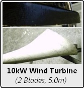
A 10 kW wind turbine blade set has been built for use with the 10 kW, 15 phase Axial flux pancake generator. When attached to the turbine it is estimated to produce approx 4-5 kW of electrical power at 50% efficiency with 8-10 kW of mechanical power driving the generator. The total cost of the turbine blades was AU$405 and the blades were constructed with typical home-workshop tools.Click here to read more...
1.8 Metre Diameter Carbon Fibre Turbine Blades & Generator
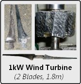
A 1 kW @ 12.5 m/s (2 kW @ 17 m/s) 1.8 metre diameter wind turbine was designed and constructed out of carbon fibre. The generator was built by converting an induction motor into a permanent magnet generator. The wind turbine blades power and efficiency has been measured at different tip-speed-ratios and a maximum efficiency of 30% at a TSR of 11.6 was recorded, verifying the blade calculators accuracy.Click here to read more...
The Darrieus Disaster
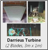
We decided to construct a prototype 2 kW Vertical Axis Wind Turbine (VAWT) using a straight blade Darrieus design. The Darrieus vertical axis windmill was patented in 1927 by the French Inventor Georges Darrieus and is a lesser known alternative to the typical 3 bladed HAWT.Click here to read more...
1.4 Metre Diameter 3-Blade Wind Turbine Construction
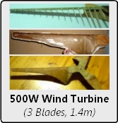
A 1.4 metre diameter wind turbine was designed and constructed out of kevlar/glass composite material. The blades have been designed to produce useable power in 30 km/h (8 m/s, 150 W) to 60 km/h (16.6 m/s, 1 kW) wind speeds. This 3-blade turbine was constructed using an inverse camber NACA2412 airfoil. The blade power and efficiency was measured at various tip-speed-ratios.Click here to read more...
- Generators
10 kW Axial Flux Pancake Generator for 2-Blade Wind Turbine
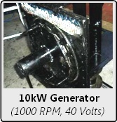
A 10 kW permanent magnet electric generator has been built and tested for use with a high tsr 5 m blade diameter wind turbine. The system was configured for 15 phase, 15 coils and 16 poles. Each coil is individually rectified to dc, reducing cogging and allowing better control over the output voltage.Click here to read more...
Construction of a Wind Turbine Dump-Load Charge Controller
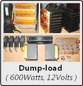
Overcharging lead-acid batteries shortens life and capacity. If the battery voltage is not kept below 14.4 Volts permanent capacity loss will occur. Voltage regulation is typically achieved by either stopping the wind turbine by shorting the generators EMF or by diverting (dumping) the power into a resistive load (heater). A universal 4-stage dump-load charge controller circuit (with load) was designed and built.Click here to read more...
- Chemistry
Microwave Chemistry Reactor
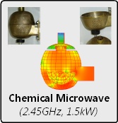
In the course of investigations into microwave assisted chemical reactions, problems were encountered due to the reaction scale upon which many commercial reactors are currently operating. Obtaining reasonable quantities of material (more than 10g) became laborious and it was also discovered that many solvents with low dielectric absorption were heated due to the ferrite core of the stirrer bar heating up.Click here to read more...
Dielectric Loss Factor (e") Measurement Over RF Frequencies Between 0.1 - 40.0 GHz for Common Organic Chemicals.

Using an Agilent Network Analyzer with open ended dielectric measurement probe (85070e dielectric probe kit), the ‘loss factor’ (e’’) of common organic solvents has been measured between the range 0.1 to 40.0 GHz. Measurements were conducted in 250 mL pyrex reaction vessels filled with 125 mL of solvent, the end of the probe submersed to a depth of 5 mm.Click here to read more...
Deconstruction of a 300 MHz Cryomagnet for NMR Spectroscopy
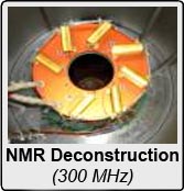
A decommissioned 300 MHz (7 T) superconducting cryomagnet was deconstructed and the insulation necessary to house the superconducting magnet at 4 K was progressively removed. The liquid nitrogen and liquid helium vessels were removed separately. The magnetic core was then dismantled.Click here to read more...
- Tools
General Unit Converter
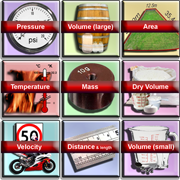
Short calculations are fast to carry out using a calculator application designed specifically for each task. Software written to simplify our ongoing research is incorporated into web based apps. Apps for domestic use have been designed upon request as a range of separate calculators.Click here to go to app...
Wind Turbine Blade Calculator
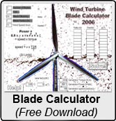
Efficient design of wind turbine blades requires solving several equations involving the lift coefficient and angle of attack for the airfoil of interest. This page allows you to specify the number of blades, required TSR, approx efficiency of blades, the blade radius and wind speed.Click here to read more...Click here to go to app...
Generate Wind Turbine Blade Cross-Sections: Free Airfoil Plans and Starting Guide

Free: Chord sections for 2 or 3 blade wind turbines with a radius between 0.70 and 0.80 meters (2.30 - 2.62 ft). Custom chord sections outside this range can be purchased from $4.95, please send us your specifications. Click here to go to app...
The Wind Turbine Blade Calculator Game
Wind Turbine Blade Calculator 2011: Design your own wind turbine. Specify wind turbine blade diameter, RPM and power to show 3d airfoil cross-sections. Built-in game to play.Click here to go to app...
Vintage Computer Simulator
Simulation of a Vintage Computer from the early 1970's. This is a sample of one of a great number of conversational programs. In a sense, it is like a AI program except that its responses are just good fun.Click here to go to app...