


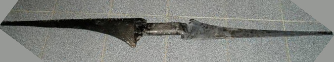
500 Watt Wind Turbine (12.5 m/s)
3-Blades (Kevlar) 1.4 Metre Diameter
3-Blades (Kevlar) 1.4 Metre Diameter
Abstract
A 1.4 metre diameter wind turbine was designed and constructed out of kevlar/glass composite material. The blades have been designed to produce useable power in 30 km/h (8 m/s, 150 W) to 60 km/h (16.6 m/s, 1 kW) wind speeds. This 3-blade turbine was constructed using an inverse camber NACA2412 airfoil. The blade power and efficiency was measured at various tip-speed-ratios. Total cost of the mould and blades was less than AU$300
Keywords: Wind power, Windmill, 3 blade wind turbine, laminar flow, inverse camber

LIST OF FIGURES


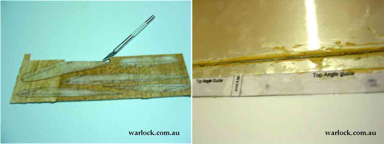
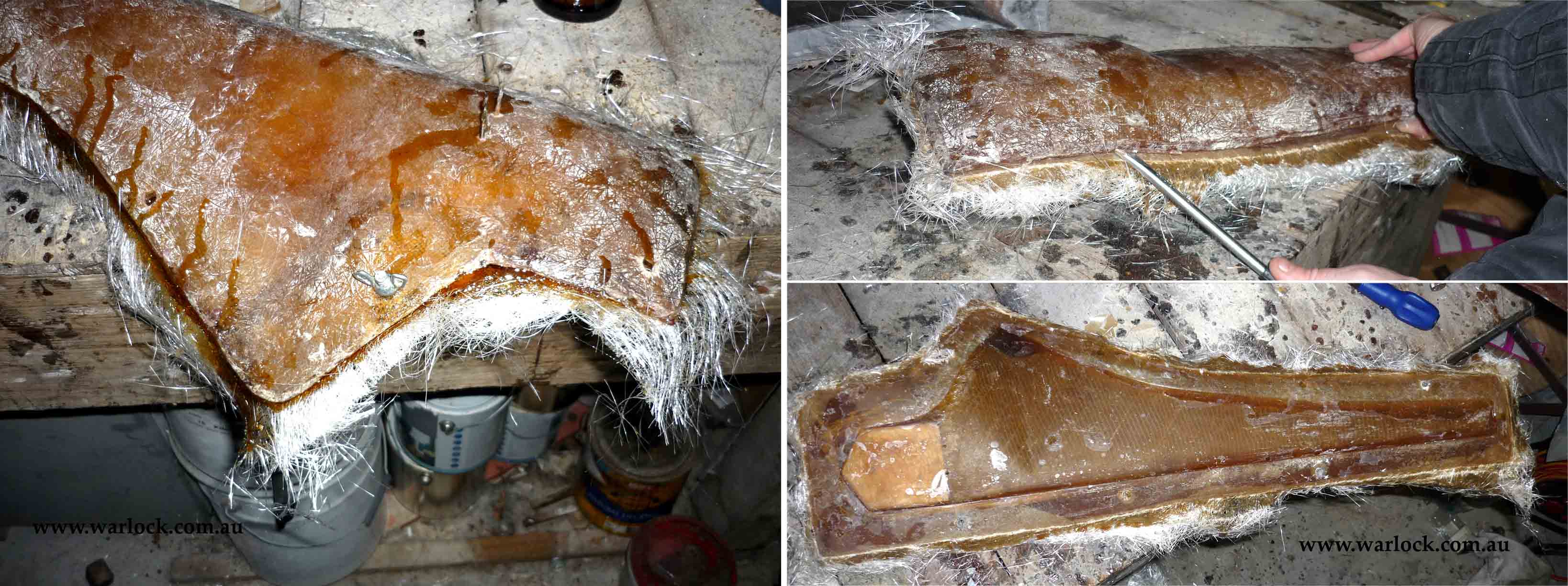
Paper stencils of airfoil shapes were glued onto balsa and cut out using a scalpel. A flat angle-guide was made using sheet metal and is used to set the angle of airfoil sections.
2. Making a plaster mould
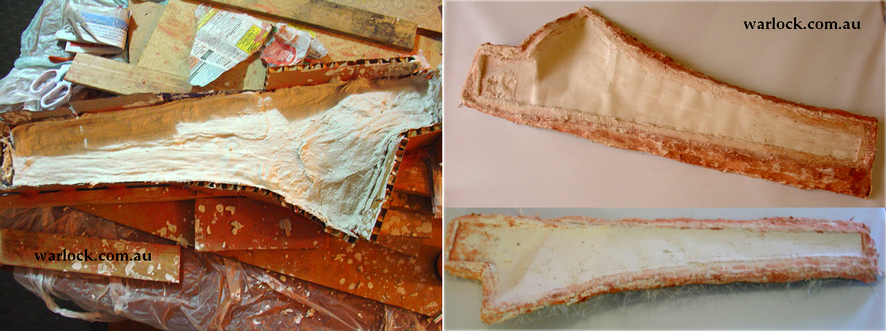
The blade skeleton was coated in white gelcoat to strengthen it and pieces of clear plastic sheet were glued on the airfoil shapes to create a wing surface. The corners and joins were sealed with aluminium tape.

Figure 3. The gel coated skeleton with plastic sheet glued to the balsa shapes (left). The final blade skeleton with border made of modelling clay (right).
Plaster and gauze was poured into the mould. After setting, the process was repeated for the other side to complete the mould.
Figure 4. Making the plaster and gauze mould (top). The two completed half moulds (bottom).
3. Making a fibreglass blade mould
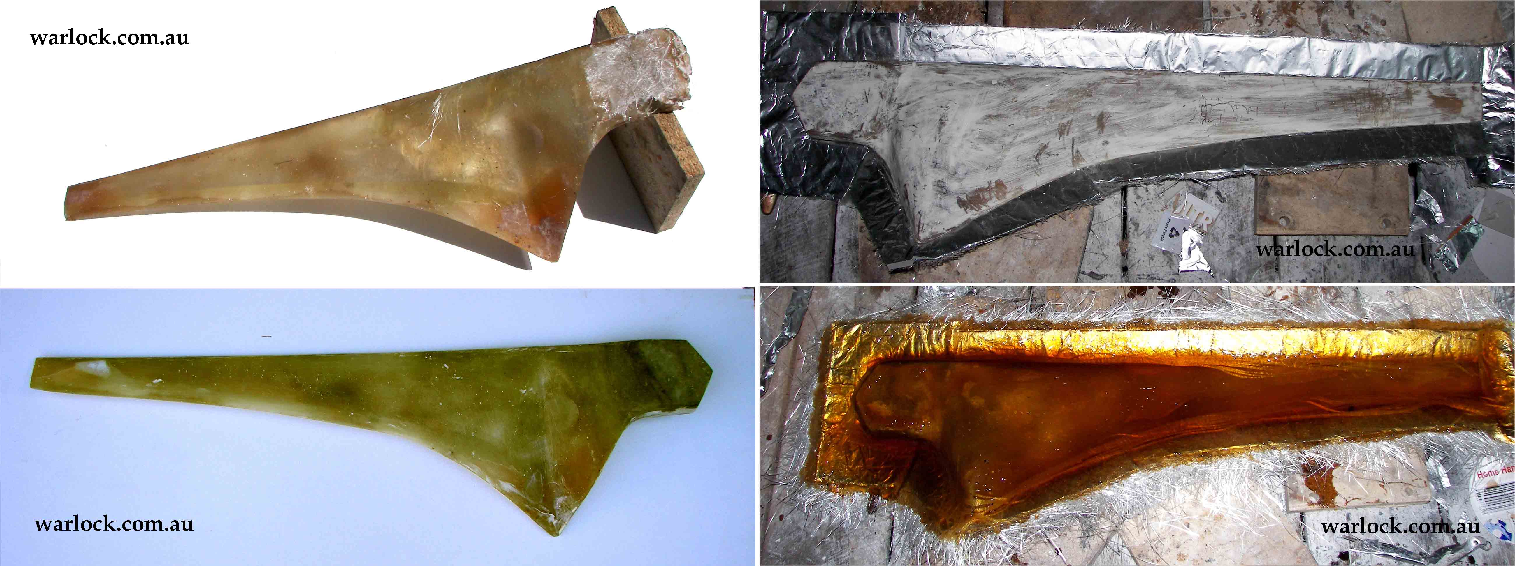
The plaster mould was waxed then filled with fibreglass to make a fibreglass wing. After curing, the plaster is removed and the wing was sanded smooth. A wooden triangle hub piece was glued in place. Cardboard and foil was used to make a border, then it was filled with fibreglass and resin to make a fibreglass mould.
Figure 5. The fibreglass blade from the plaster mould (left). Making the fibreglass mould from the blade (right).
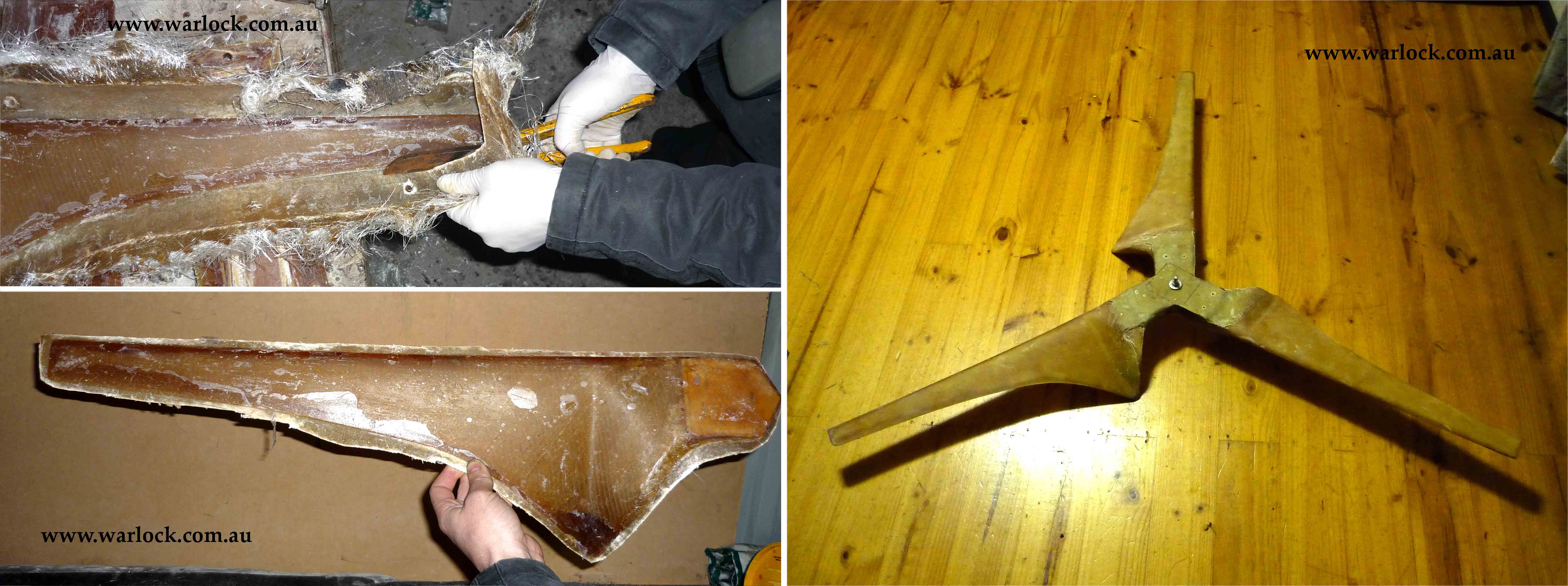
The other side of the mould was fibreglassed and the border was cut square. The mould opened easily and was waxed up before use.

Figure 6. Making the fibreglass mould (top) and waxing before use (bottom).
4. Making the blade
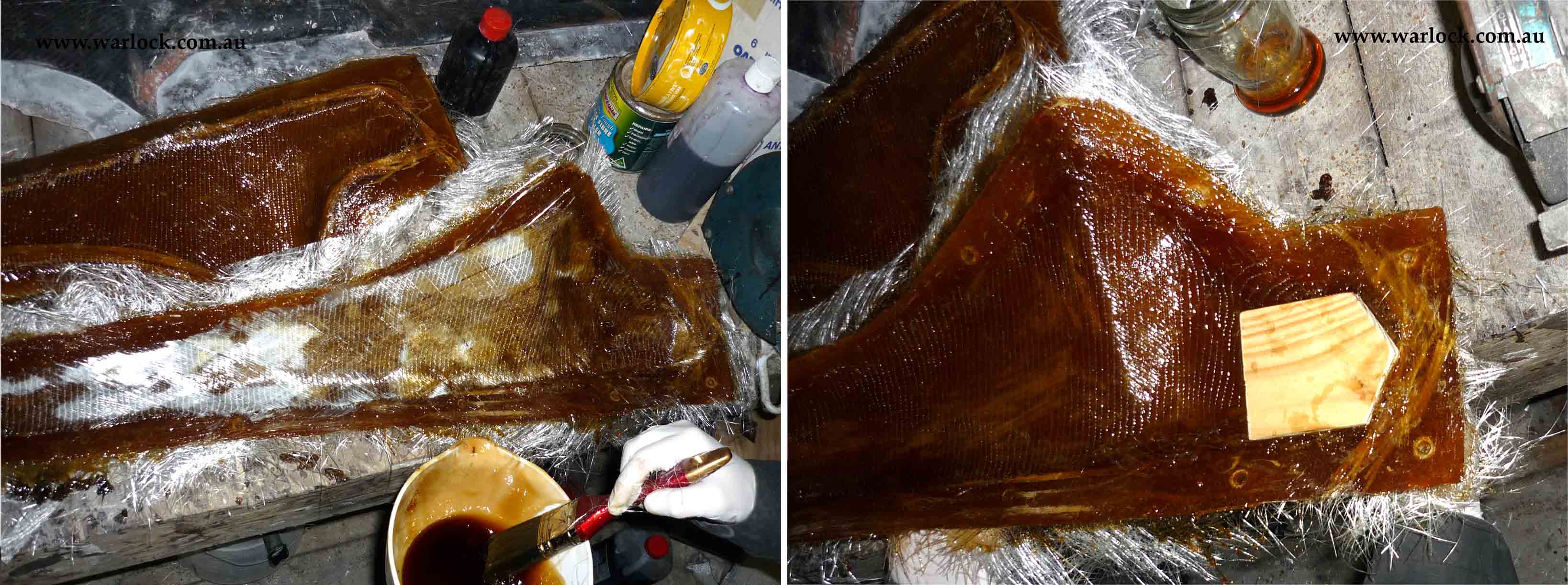
The half moulds were filled with pre-cut shapes of fibreglass and kevlar, then the resin was soaked into the glass with a paintbrush. A wooden hub is inserted at the end of the mould.
Figure 7. Half moulds being filled with glass and soaked in resin (left). A wooden hub is fitted at the end (right).
The mould halves were pressed together and tightened using bolts around the border. After the resin cured, the mould was broken apart using a knife and a screwdriver.
Figure 8. A moulded blade ready to be cured (left). Breaking the cured mould apart (right).
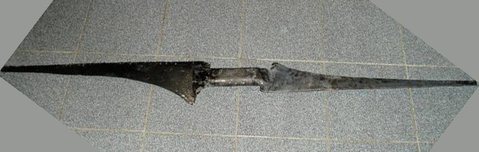
The blade was broken out of the mould and the edges were cleaned up using a pair of snips. After some sanding, each blade was wrapped in a layer of fibreglass cloth. The three blades were fitted together and reinforced using layers of fibreglass.
Figure 9. Fibreglass blades from the mould (left). The finished 3 blade set (right).


Frequently asked questions about plan orders, blade design, electrical work and generator matching can be found on our Q&A pages.
1. Construction of the blade skeleton
Related Topics


SPONSORED ADVERTISEMENT

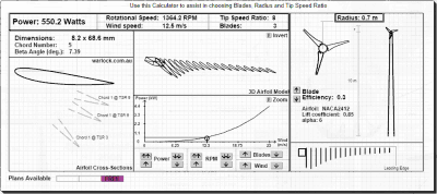
Free sample chord sections can be generated for 0.70 m to 0.80 m blades
(550 Watts - 710 Watts)
(550 Watts - 710 Watts)


The hub for the blade skeleton was made from a piece of wood that was glued onto the root section. The balsa airfoil shapes were positioned and glued along the root.
Figure 1. The airfoil shapes were constructed using balsa (left).
The root and angle-guide were made from tin sheet and wire (right).
The root and angle-guide were made from tin sheet and wire (right).
A root made from a round piece of steel rod (2 mm) is glued to the top of the angle-guide and is used to position the rounded end of each airfoil section. The root-guide was fibreglassed and sanded flat.
Figure 2. The root section glued to the hub (top). The balsa airfoil shapes glued along the root (bottom).


SPONSORED ADVERTISEMENT


4. Making the blade
The finished blades were tested using the generator shown in the 1.8 m blade wind turbine. The results are shown below.

Free sample chord sections can be generated for 0.70 m to 0.80 m blades
(550 Watts - 710 Watts).
(550 Watts - 710 Watts).
Measurement of results from the wind turbine
Note: Our method of testing turbine generates turbulent wind, affecting efficiency. The results should be used as a guide only.
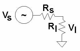
Rs is the resistance of the generator windings plus the power cable; 5.75 ohms
Rl is the resistance of the load; 6.6, 10, 15, 21.5 and 25 ohms
Power generated by the blades was calculated by dividing measured power by the efficiency of the generator. Once the blades have been characterized, a new generator will be designed.


5. Testing the wind turbine
The wind turbine was bolted to a trailer and rpm, voltage and tsr was measured by connecting the generator to a very high power multi-tap resistor. The turbine was allowed to speed up to an open circuit voltage of 65 V (666 rpm) before the resistor load was connected. The measurement method and results are presented.
Power generated by the blades is calculated using the following method:
Voltage across the resistor load was measured (Vl),
Vs = Vl x [(Rs + Rl) / Rl ]
Power produced by blades and lost in generator, power cable and resistor load is given by;
P = V2/R
P = Vs2 / (Rs+Rl)
The results from the wind turbine test are included below.

| 25 ohm | 21.5 ohm | 15 ohm | |
| 30 km/h | 756 | ||
| 40 km/h | 1040 | 844 | |
| 45 km/h | 1299 | ||
| 50 km/h | 1425 | 1143 | 2098 |
Rotational speed (rpm)
| 25 ohm | 21.5 ohm | 15 ohm | |
| 30 km/h | 177 | ||
| 40 km/h | 335 | 249 | |
| 45 km/h | 521 | ||
| 50 km/h | 628 | 457 | 452 |
Power (watts)
| 25 ohm | 21.5 ohm | 15 ohm | |
| 30 km/h | 177 | ||
| 40 km/h | 335 | 249 | |
| 45 km/h | 521 | ||
| 50 km/h | 628 | 457 | 452 |

Figure 10. Measured power output vs. wind speed

Figure 11. Measured RPM vs. wind speed


Figure 12. Measured efficiency vs. TSR


System cost (AUD)
Balsa, glue, tin sheet $10
Gel coat $40
Plastic sheet, plaster $25
Modelling clay $23
Vinyl ester resin $110
Fibreglass cloth/mat $80
Total cost $288

6. Total cost of the wind turbine


| Figure | Page | |
| 1 | Left: The airfoil shapes constructed using balsa. Right: The root and guide made from tin sheet and wire. |
1 |
| 2 | Left: The root section glued to a hub. Right: The balsa airfoil shapes glued along the root. |
2 |
| 3 | Left: Gel coated skeleton with plastic sheet glued to balsa shapes Right: Final blade skeleton with border made of modelling clay | 2 |
| 4 | Left: Making the plaster and gauze mould. Right: The two completed half moulds. |
2 |
| 5 | Left: The fibreglass blade from the plaster mould. Right: Making the fibreglass mould from the blade. |
3 |
| 6 | Left: Making the fibreglass mould. Right: Waxed mould before use. |
3 |
| 7 | Left: Half moulds being filled with glass and soaked in resin. Right: A wooden hub is fitted at the end. |
3 |
| 8 | Left: A moulded blade ready to be cured. Right: Breaking the cured mould apart. |
3 |
| 9 | Left: Fibreglass blades from the mould. Right: The finished three blade set. |
4 |
| 10 | Measured power vs. wind speed | 5 |
| 11 | Measured RPM vs. wind speed. | 5 |
| 12 | Measured Efficiency vs. TSR | 6 |
| 13 | Measured Power | 6 |

Free plans for 500 W
blades with each purchase
blades with each purchase
| 25 ohm | 21.5 ohm | 15 ohm | |
| 30 km/h | 6.6 | ||
| 40 km/h | 6.8 | 5.5 | |
| 45 km/h | 7.5 | ||
| 50 km/h | 7.4 | 6.0 | 5.2 |
A border was made out of modelling clay to create a mould for the plaster to be poured into.

Related
Articles
Articles
Tip speed ratio

, 5 Metre Diameter Carbon Fibre Blades")


 Measurement Over RF Frequencies Between 0.1 - 40.0 GHz for Common Organic Chemicals.")


1.4 Metre Diameter 3-Blade Wind Turbine Construction

