


Design custom blades for your generator and calculate power output at each wind speed.


Free sample chord sections can be generated for 0.70 m to 0.80 m blades (550 Watts - 710 Watts).


Free plans for 500 W blades with each purchase.


Enable Ads for www.warlock.com.au
SPONSORED ADVERTISEMENT


10 kW (13 m/s) 5 m Diameter Carbon Fibre Wind Turbine Blades
Abstract
A 10 kW wind turbine blade set has been built for use with the 10 kW, 15 phase Axial flux pancake generator. When attached to the turbine it is estimated to produce approx 4-5 kW of electrical power at 50% efficiency with 8-10 kW of mechanical power driving the generator. The total cost of the turbine blades was AU$405 and the blades were constructed with typical home-workshop tools.
Keywords: Wind power, Wind turbine blade construction, 10 kW wind turbine, Carbon fibre wind turbine blades


LIST OF FIGURES


1. Constructing the interior of the wind turbine blades
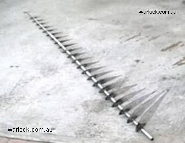
Figure 1. Steel blade core
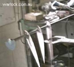
Figure 2. Skeleton airfoil blade one


Figure 3. Skeleton airfoil blade two


SPONSORED ADVERTISEMENT

Figure 4. Skeleton filled with polyurethane foam
The skeleton was filled with expanding polyurethane foam (1kg Suprasec 5005, 1kg Daltolac GP33) and sanded into shape.


2. Constructing the exterior of the wind turbine blades

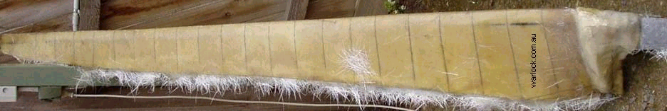
Figure 6.
Blade after being covered in chop strand matt fibreglass
The blade was coated in a layer of vinyl ester resin and once the resin had cured, 220 g chop strand matt fibre glass was used to fibreglass the blades, this was does several times with sanding to ensure a smooth finish.
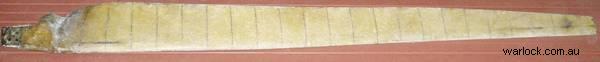
Figure 7.
Blade after being covered in bi-axial glass cloth fibreglass
400g bi-axial glass cloth was wrapped around the blade and fibre glassed in place. It was lightly sanded before applying another layer of chop strand matt.
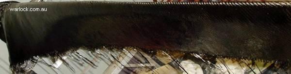
Figure 8.
Blade after being covered in uni-directional carbon fibre
Chop strand matt was sanded into shape before applying the final layer of 197g uni-directional carbon fibre. The carbon fibre is lightly sanded to form a smooth flat blade


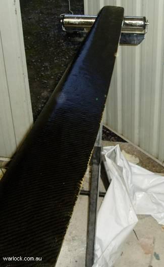
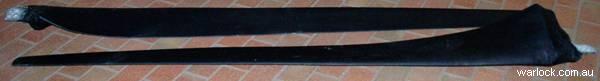
Figure 10.
Completed 5 m wind turbine blades
Running at a TSR of 12.5 the generator should output 4kW electrical power, requiring 8kW mechanical power
Rotational Torque = 121.45 N.m
Rotational Speed = 620.7 RPM
Mechanical Power = 7894.3 Watts
Blade Efficiency = 0.3
TSR = 12.5
A TSR of 12.5 is a better match to the generator
Running at a TSR of 9, the generator should output 2kW electrical power, requiring 4kW mechanical power
Rotational Torque = 224.91 N.m
Rotational Speed = 446.9 RPM
Mechanical Power = 10,525.7 Watts
TSR = 9
Blade Efficiency = 0.4
Output of system at maximum generator output (generator efficiency of 50%)
3. Calculated output of the wind turbine system


At a total cost of $1,278 including the generator, a wind turbine capable of producing 4-5kW
electrical power makes a very cheap alternative for power production especially in remote areas.
System cost (AUD)
Steel $25
Polyurethane $40
Matt, cloth, resin and initiator (MEKP) $220
Carbon fibre (increased strength, not essential) $120
Total cost $405
Equipment used
Arc welder
Grinder
Drill
Wood saw
Sand paper
Fibreglass rollers
Paint brushes
Conclusion
4. Total cost of the wind turbine blades


Frequently asked questions about plan orders, blade design, electrical work and generator matching can be found on our Q&A pages.
Abstract


A TSR of 12.5 is a better match to the generator
Output of system at maximum generator output (generator efficiency of 50%)

3. Calculated output of the wind turbine system

At a total cost of $1,278 including the generator, a wind turbine capable of producing 4-5kW electrical power makes a very cheap alternative for power production especially in remote areas.
System cost (AUD)
Steel $25
Polyurethane $40
Matt, cloth, resin and initiator (MEKP) $220
Carbon fibre (increased strength, not essential) $120
Total cost $405
Equipment used
Arc welder
Grinder
Drill
Wood saw
Sand paper
Fibreglass rollers
Paint brushes
Conclusion

4. Total cost of the wind turbine blades

2. Constructing the exterior of the wind turbine blades
Figure 5. Polyurethane foam blade after sanding
Figure 6. Blade after being covered in chop strand matt fibreglass
Figure 7. Blade after being covered in bi-axial glass cloth fibreglass
Figure 8. Blade after being covered in uni-directional carbon fibre
Figure 10. Completed 5 m wind turbine blades
Figure 9. Blade after sanding the carbon fibre
Rotational Torque = 224.91 N.m
Rotational Speed = 446.9 RPM
Mechanical Power = 10,525.7 Watts
Blade Efficiency = 0.4
TSR = 9
Running at a TSR of 9, the generator should output 2 kW of electrical power, requiring
4 kW mechanical power
4 kW mechanical power
TSR = 12.5
Blade Efficiency = 0.3
Mechanical Power = 7894.3 Watts
Rotational Speed = 620.7 RPM
Rotational Torque = 121.45 N.m
Running at a TSR of 12.5 the generator should output 4 kW electrical power, requiring 8 kW mechanical power
Chop strand matt was sanded into shape before applying the final layer of 197g uni-directional carbon fibre.
The carbon fibre is lightly sanded to form a smooth flat blade.
The carbon fibre is lightly sanded to form a smooth flat blade.
The blade was coated in a layer of vinyl ester resin and once the resin had cured, 220 g chop strand matt fibre glass was used to fibreglass the blades. Several layers were used with sanding to ensure a smooth finish.
400g bi-axial glass cloth was wrapped around the blade and fibre glassed in place. It was lightly sanded before applying another layer of chop strand matt.
Related Articles
| Figure | Page | |
| 1 | Steel blade core | 1 |
| 2 | Skeleton airfoil blade one | 1 |
| 3 | Skeleton airfoil blade two | 2 |
| 4 | Skeleton filled with polyurethane foam | 2 |
| 5 | Polyurethane foam blade after sanding | 2 |
| 6 | Blade after being covered in chop strand matt fibreglass | 3 |
| 7 | Blade after being covered in bi-axial glass cloth fibreglass | 3 |
| 8 | Blade after being covered in uni directional carbon fibre | 3 |
| 9 | Blade after sanding the carbon fibre | 4 |
| 10 | Completed 5 m wind turbine blades | 4 |
The airfoil shapes were printed using a computer. The printouts were glued on 1 mm steel sheet and cut out.
The steel airfoil cut-outs were welded on steel tube, with the angle set using a protractor against a plumb line.

, 5 Metre Diameter Carbon Fibre Blades")


 Measurement Over RF Frequencies Between 0.1 - 40.0 GHz for Common Organic Chemicals.")


1.4 Metre Diameter 3-Blade Wind Turbine Construction

